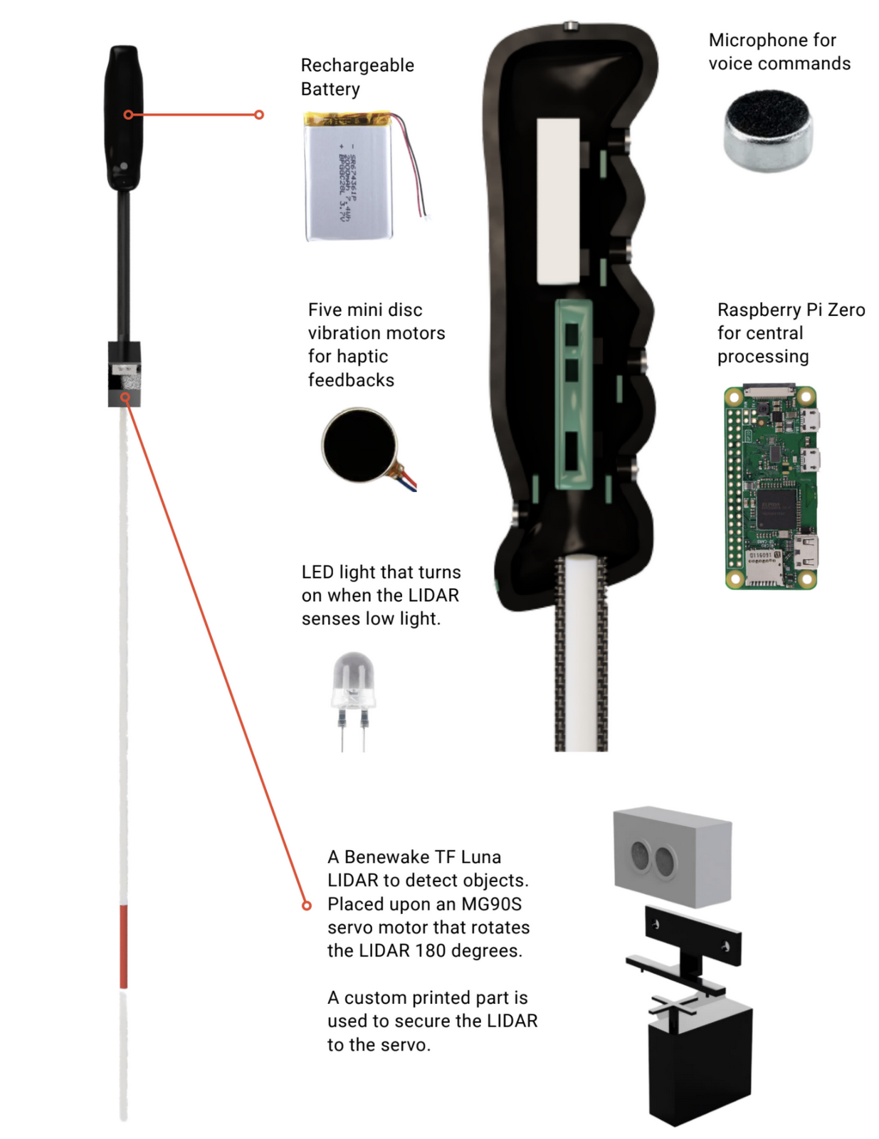
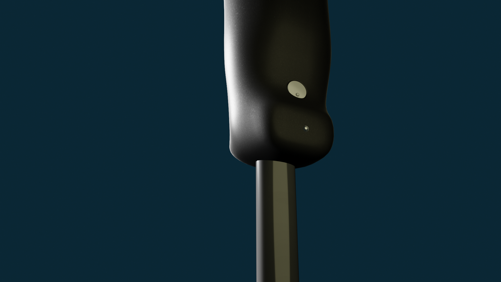
Opticane's uses a LIDAR on a servo to control its LIDAR capabilities for a 180° field of view. It uses an LED to allow people to know of your presence in dark areas, uses a small microphone for voice commands, and five mini disc vibration motors for haptic feedback, where each motor makes direct contact with each one of your fingers. These components are then all combined together using a Raspberry Pi Zero powered by a rechargeable battery.
Currently, these components are all housed in custom 3D printed parts, but in the future we would like to move to a rubber handle to negate any cross-vibrations as well as use a lighter carbon fiber material for the cane to decrease the overall weight.
Many smart canes in the market use SONAR or ultrasound technology. These systems can generate a lot of noise when in use and SONAR has issues detecting objects with smooth surfaces. Given a lot of buildings are made with sleek glass and metal this can be an issue for such canes in modern cities. That’s why at Opticane we decided to use LIDAR technology to remove these issues and allow for quiet and discreet operation of the cane.
The LIDAR we have chosen to use is the Benewake TF Luna LIDAR, advertised as the world’s smallest LIDAR. This allows it to be mounted non-intrusively onto the cane and with a maximum reach of up to 8m it allows it to detect most objects in a user's vicinity. In order to rotate the LIDAR to give it a full 180 degree field of vision, the LIDAR is mounted to a MG90S mini servo motor. The motor’s small size allows it to be fitted discreetly under the LIDAR to provide all the functionality but still give the cane a sleek look.
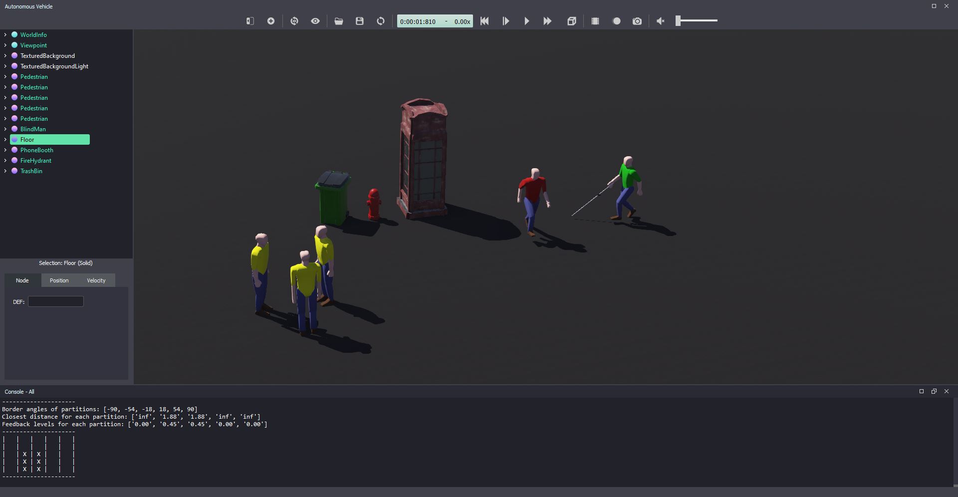
We developed a simple but effective algorithm to partition and process the LIDAR data. The algorithm takes in all 180 LIDAR readings from its field of vision then segments that data into 5 partitions. These partitions represent the left, front left, front, front right and right of the user. Then for each partition we find the 3 closest distance readings in that partition and take the weighted average of them, with the closer the distance the greater the weighting. This weighting also disregards distances less than 0.2m since these readings are unreliable. This all allows for our readings to account for potential noise in the LIDAR.
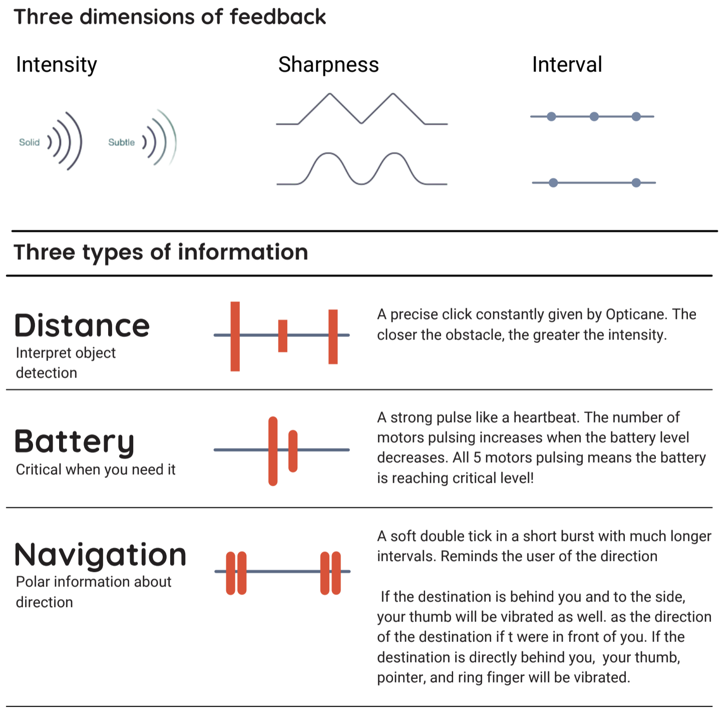
Haptic feedback is the main form of output for Opticane. Five mini disc vibration motors located in the grooves of the handle give comfortable access and an intuitive feel to the haptic feedback. With these motors, we have our own primitive haptic language that we like to call Vibraille where intensity, sharpness, and interval are varied to generate messages
.
Five average distances in each partition, calculated from LIDAR data, are translated to vibration feedback levels. The closer the distance the greater the vibration. These vibrations are then sent to the multiplexor which is in turn sent to the corresponding mini disc motor. The vibration felt for distance information is a short 'click' given at constant intervals.
However, Vibraille is not just reserved for obstacle distance information. Battery Life Indication uses Vibraille by vibrating a number of motors - the more motors vibrating the less battery is left. We decided to go with 'more motors equals less battery' as research shows more haptics implies more alertness in the user and you want to alert the user more when the battery is low. The vibration itself is a strong pulse like a heartbeat and when the user feels five of these heartbeat vibrations they know the battery is at a critically low level.
Each vibration motor also has a small bump on it to indicate which direction the motor corresponds to with haptic feedback. This can be changed to braille in the future.
A big issue facing visually impaired users is travelling at night. Unlike sighted people, the visually imapired people have trouble making themselves more visible to pedestrians, cyclists, etc. [10] We decided to add a feature to our cane where if the LIDAR detects low light an LED will turn on bringing more visibility to the user. The LIDAR detects low light through its 'Amp' value- if the amp value (signal strength) is less than 100 the signal is underexposed and therefore the environment is dark.
We also decided to go with a soft warm light LED as well, to prevent pedestrians etc being dazzled by a brighter LED light.
Opticane understands voice commands for checking battery levels and navigation. This is implemented in Python through its SpeechRecognition library and uses CMU Sphinx Speech Recognition Engine for offline speech recognition. [11]
The basic commands we have implemented so far include:
| Command | Description |
|---|---|
| Check Battery Life | Engages the aforementioned haptic feedback mode to show the user how much battery is left via vibration |
| Save location as <Location> | Saves the longitude and latitude of a named location, <Location>, to Opticane’s system |
| Where is <Location>? | Retrieves the longitude and latitude of the named location, <Location>, and calculates directions based on the current location of the user |
| Delete <Location> | Deletes the named location, <Location>, from Opticane’s system |
| Stop Navigation | Stops the haptic feedback navigation which is providing haptic directions to get to a saved location. |
Navigation is a huge issue for the visually blind. Jack Loomis from the University of California Santa Barbara points this out in a paper discussing the issue saying how "visually impaired people do not have the benefit of recognising landmarks, buildings etc as an indication of location." [12] Additionally voice-based map technologies such as Google Maps are limited in the number of cities and are mostly English based. We therefore proposed an additional feature where users can receive navigation information to get to a specified location via a Haptic Feedback while removing the issue of translation voice-based maps have.
The Haptic Navigation works through a combination of the aforementioned speech recognition and Opticane’s GPS module. The GPS module is attached to Opticane’s Raspberry Pi and can receive longitude and latitude data of the user’s current location. If the user wants directions to return to a location, they can use the "Save location as <Location>" to save the longitude and latitude of the current location with an associated name to the Opticane’s system.
This location can then be recalled with the "Where is <Location>?" where Opticane’s system recalls the named location <Location>, retrieves the longitude and latitude of said location and using the current longitude and latitude calculates the direction the user needs to go in.
The Haptic Motors that correspond to the directions the user should take are similar to obstacle detection mapping: middle and index finger means right, ring and pinky means left, and thumb means forward.
Since, unlike the battery life haptics, the navigation haptics have to be differentiated from the obstacle detection haptics in order to not confuse the user. As a result, we use a different vibration pattern for navigation than obstacle detection: a soft double tick 'burst' of vibration in longer intervals to regularly remind the user of the direction.
A long lasting battery life was essential to the design of our product. After all, we wouldn’t want to inhibit our users by forcing them to recharge the cane every few hours.
Assuming every aspect of the device is on at all times, i.e. motors constantly going off at full power, we can calculate an Lower Bound on the battery life via an Upper Bound on the current draw.
Upper bound on Current Draw: 70mA (LiDAR) + 375mA (MiniDisc Motors) + 120mA (Servo Motor) + 20mA (Pi Zero) = 580mA
Battery Consumption = 1800mAh/580mA = ~3.1 hours of battery life
However this is unrealistic as to how the product operates. From studying the video of the servo motor, it takes 1.5 seconds to complete its rotation and for the Pi to buffer all LiDAR data. However sources indicate that the actual motor time for such an operation is 0.3s. [13] So the motor is only drawing 120mA 20% of the time, the other 80% it is idle waiting for LiDAR data to be processed. At this stage it will only draw 10mA. The MiniDisc Motors will also not constantly draw their 75mA maximum, the average terminal output shows the miniDisc motors are usually not all engaged at once and maybe only one or two are showing any reading at one time. So you could take an average 80mA (say one motor is operating at mid level 20mA and another at high level 60mA)
Therefore we can now accurately construct a more realistic battery life consumption.
Total Current Draw: 70mA (LIDAR) + 80mA (MiniDisc Motors) + (120*0.2+10*0.8)mA (Servo Motor) + 20mA (Pi Zero) = 202mA
Battery Consumption = 1800mAh/202mA = ~8.91 hours of battery life
Therefore with the current battery, Opticane can reach almost a full working day of battery life. There are no concerns if you go out in the morning of Opticane dying before you get back in the evening.
While this battery life is good, in the future Opticane would look at getting a better battery for the cane. For example the Xenta Power Bank
can power our Upper Bound on current draw, 580mA, for up to 18 hours. However the weight of such a battery at 180g, would also need to be factored into the design of our cane, which we are trying to keep as lightweight as possible. Battery life vs portability is a classic engineering issue that through further research experimentation we would try to resolve.
For our final hardware prototype of the cane, we’ve endeavoured to find the smallest and lightest hardware components possible that still allow for the same level of functionality. In a 2013 study, it was found that lighter canes made of carbon fibre (around 113g) did not strain the wrist and upper muscles as much as conventional canes weighing around 252g- “results indicated that the newly developed cane reduced the loads on muscles by approximately 50%. This is why in the final product, we looked into a lighter carbon-fibre cane that could be used. Additionally it gives us parameters to work with in terms of 252g is the acceptable cane weight so we should select parts for the cane handle to ensure the combined weight of the carbon fibre cane and the handle is less than 252g.
In the final prototype we did use a slightly heavier casing made of plastic material for the handle and other parts. So the total weight for the prototype is:
Total Weight: 182g (cane + handle + casing) + 14g (servo motor) +9g (Raspberry Pi) + 21g (battery) +5g (LIDAR) = 231g
However in the actual product we would use a lighter cane made of carbon fibre, around 113g, plus a lighter rubber mould which we estimate is around 20g. Therefore the total weight of the final product would be around 182g.
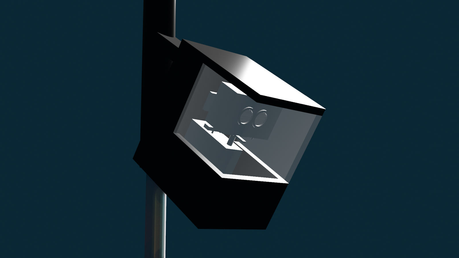
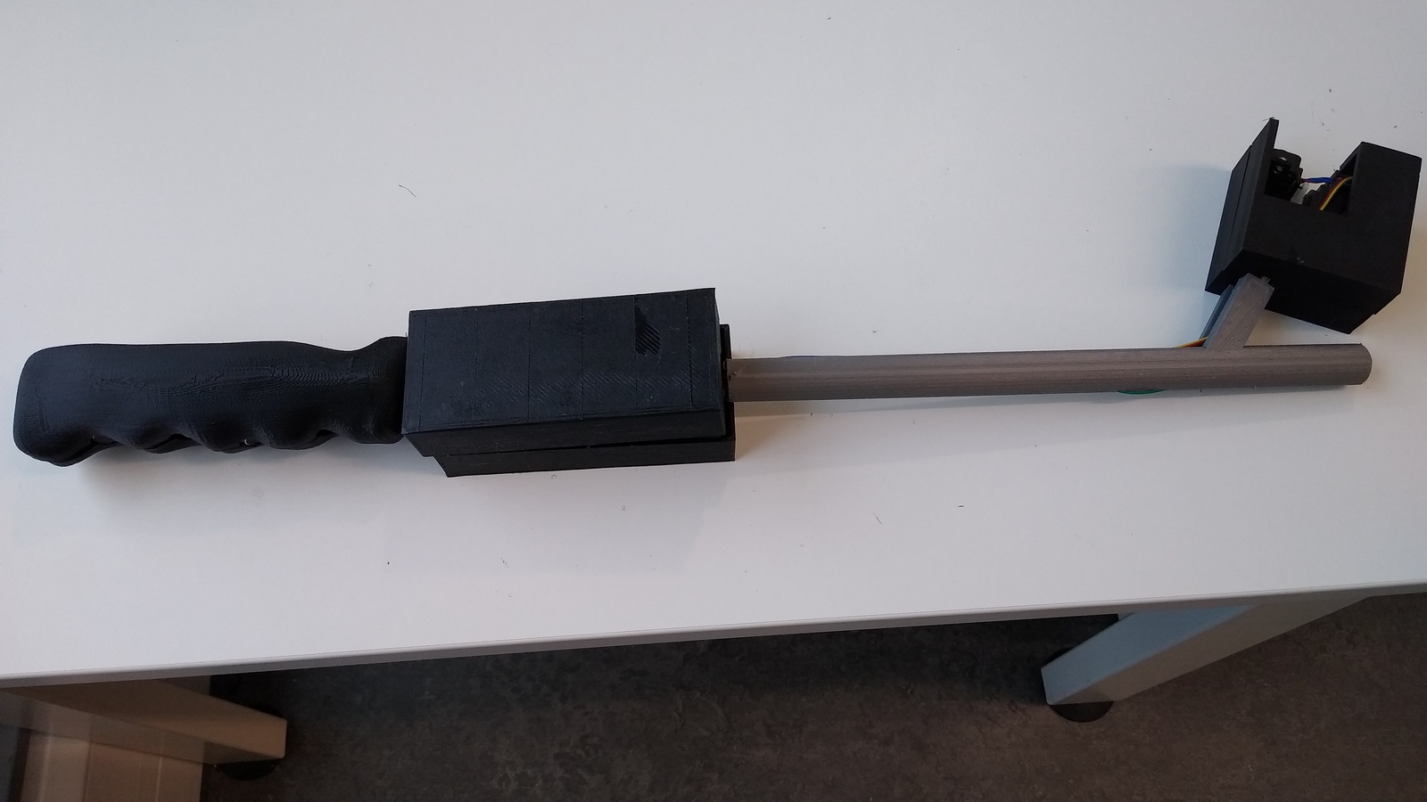
To demonstrate the feasibility of Opticane, we 3D modeled and printed the parts for a minimum working prototype. This included printing the handle, a portion of the cane, a custom piece to secure our LIDAR to the servo, and the LIDAR casing. Afterwards, the technician team fitted the vibration motors, Raspberry Pi, battery, servo, and LIDAR into their respective casings to create a working prototype that could perform accurate object detection.
In addition to our prototype, to demonstrate the more technically complex aspects of Opticane, we used a Webots simulation. In this simulation, we have modeled human controllers swinging a LIDAR-mounted cane from side to side and reacting to object detection values received from the LIDAR. The simulation also uses keyboard input to activate voice commands and successfully presents Opticane's haptic navigation system and battery checking capabilities.
With the simulation, we were able to more easily illustrate and understand the possible use cases of Opticane in real world scenarios with all of its technical complexities. It also allowed us to perform pseudo-user testing which was very beneficial given the restraints of the pandemic.